AMBER Lab
Advanced Multiscale Building Energy Research Lab
The AMBER Lab consists of a state-of-the-art environmental chamber with its own semi-custom air handling unit that supplies filtered and conditioned air that can be used for laboratory validations (see schematic in Fig. 1). The dimensions of the AMBER Lab chamber are ~15.5 x 18 x 12 ft3 (4.5 x 5.5 x 3.6 m3). The top view of the chamber has dimensions of 5.38 m (length) x 4.46 m (width) x 2.67 m (height) and can accommodate full-size drywall panels vertically. The environmental chamber has the ability to control supply and return air flow rate, supply and return relative humidity, supply and return dry bulb temperature, and outdoor air supply. It has a dedicated air handling unit located on the roof of Brown Hall at Colorado School of Mines.
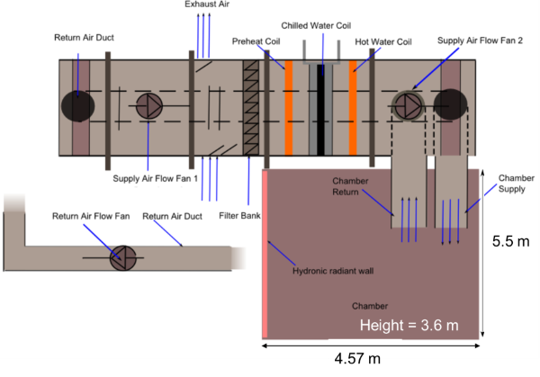
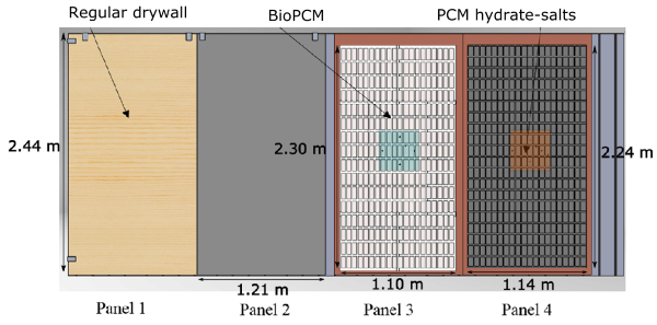
Fig. 2: Drywall arrangement in experiment with phase change materials
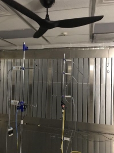
Fig. 3: Bidirectional ceiling fan and experimental setup to measure air flow
Chamber & Ceiling Fan
The chamber serves as a piece of equipment that provides specific environmental conditions necessary for ventilation experiments, indoor air quality assessments, thermal performance of wall assemblies, and environmental perceptions of occupants. Fig. 2 shows an experimental arrangement for different wall panels with phase change materials.
Some of the chamber’s unique characteristics include:
- Supply airflow rate range of 50–900 cfm that is possible by using very frequency drives (VFD) in the supply and return fans
- Percent of outdoor air: 0–100%
- Hydronic wall system: 1.6 kW glycol wall on one 18-ft wall with its own dedicated cooling and heating system
- Control system: able to communicate with MATLAB and EnergyPlus via Modbus RTU communication
- Chamber: controlled with a 6-core workstation
The chamber also has a Haiku bidirectional ceiling fan with a remote control. This allows us to simulate spaces with a ceiling fan and/or study the airflow impacts ceiling fans produce. Fig 3. shows an AMBER research study in which airflow inside the chamber was analyzed at different ceiling fan speeds.

Fig. 2: Drywall arrangement in experiment with phase change materials

Fig. 3: Bidirectional ceiling fan and experimental setup to measure air flow
Hydronic Radiant Wall
The chamber is equipped with a hydronic radiant wall (Fig. 4, left) that has the ability to maintain a constant and variable surface temperature independent of the indoor air temperature to mimic external boundary conditions such as an exterior wall subject to solar radiation. The hydronic radiant wall is used to set-up the outside boundary conditions in the chamber. Outside the chamber, a three-speed pump, mini boiler, control valve, and chiller (Fig. 4, right) allow for heating and cooling applications. The radiant wall temperature is controlled by a three-way mixing valve and a pressure-independent control valve. Measurements for the radiant wall include flowrate supply and return water temperature.
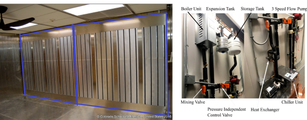
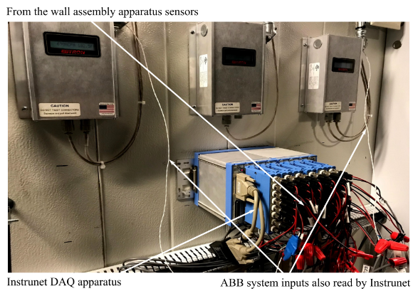
Fig. 5: Data acquisition (DAQ) apparatus
Data Acquisition
The chamber also has separate data acquisition (DAQ) for collecting all data related to heat flux and temperature measurements (Fig. 5). There are two DAQ units, which the sensors communicate with: (i) ABB control unit (ii) InstrunetTM DAQ apparatus:
- The ABB main control unit controls the HVAC system and monitors information related to the chamber control system and the air handling unit, such as chamber (supply and return) temperature, humidity, VOC, and flow rates
- The Instrunet DAQ captures data from all sensors needed for heat transfer experiments

Fig. 5: Data acquisition (DAQ) apparatus
Control
The chamber has three main control modes: (i) Supply Air Temperature based (DAT), (ii) Room Air Temperature based (RAT), and (iii) variable air volume based (VAV). Each of the modes has PID controller units. The AMBER Lab has more than 60 thermistors, 8 hot-sphere omnidirectional anemometers, 4 heat flux meters, 2 infrared temperature sensors, 1 infrared camera that can be controlled remotely, and 40+ plug load meters.
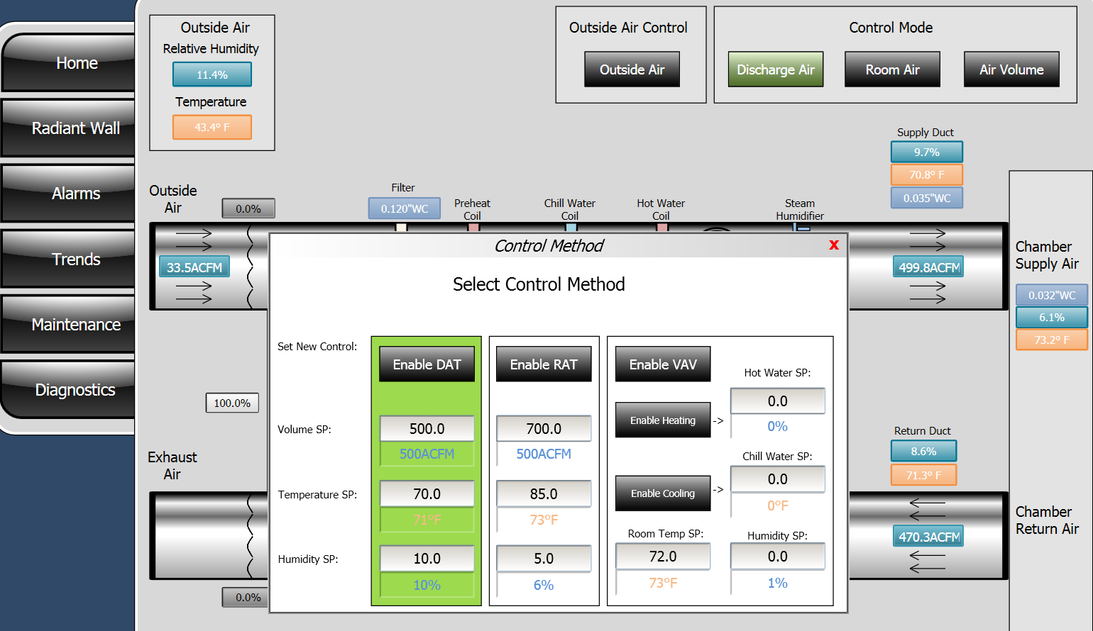
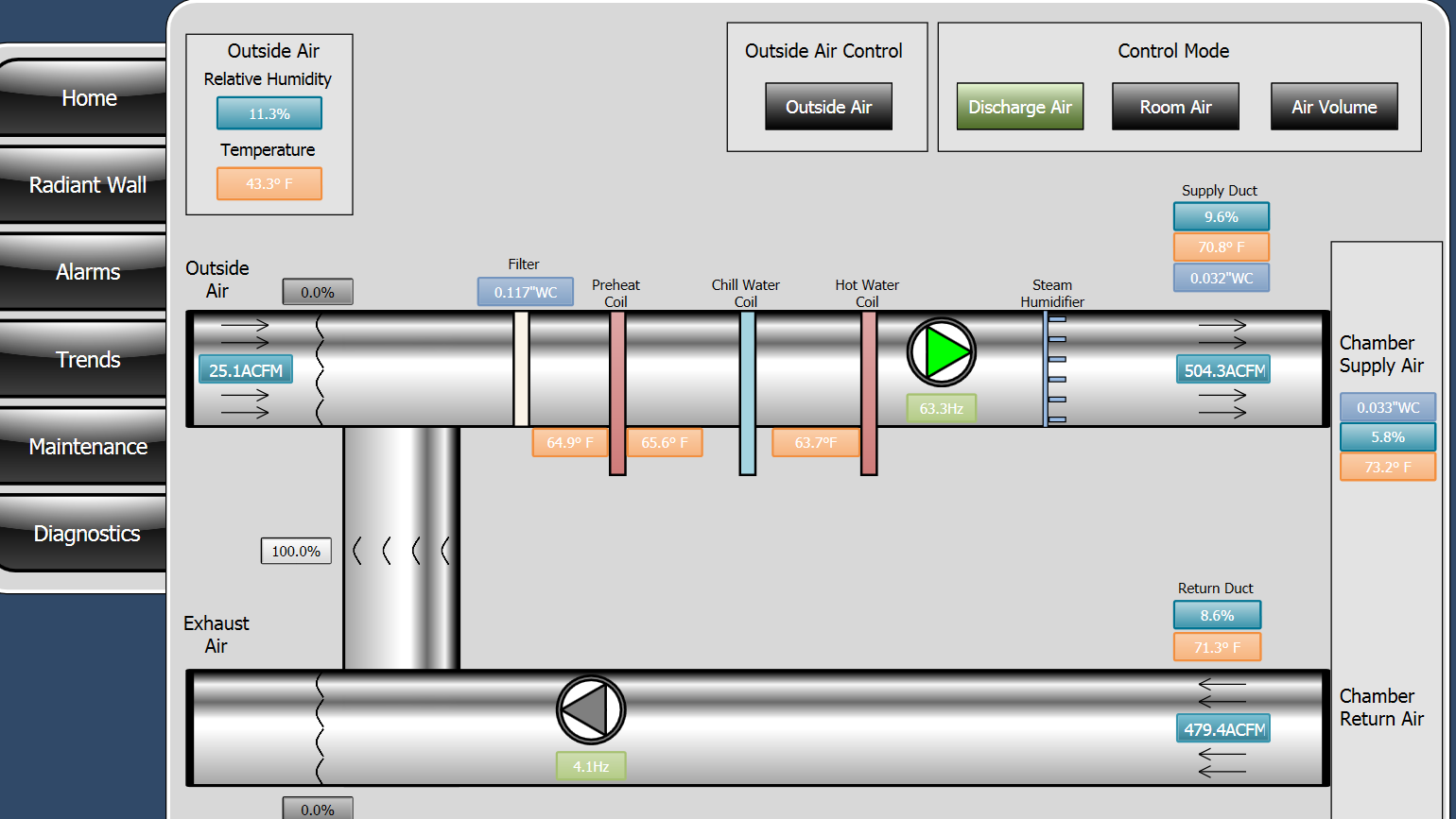


Fig. 6: Digital control system


